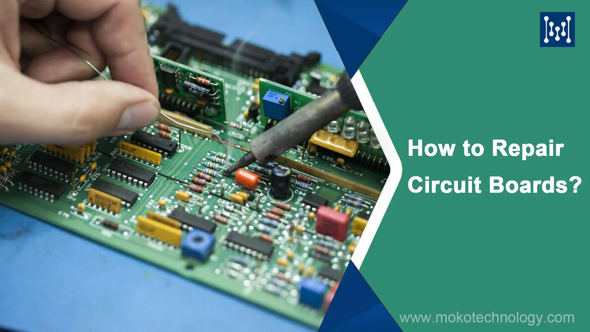
Knowing how to repair a circuit board can save you a significant amount of cost compared to replacing the entire device. Repairing the PCB alone can cut costs by 60%-80%. Moreover, it helps reduce electronic waste and minimizes the environmental impact associated with manufacturing new circuit boards. With 20 years of experience in PCB manufacturing, we clearly understand why boards fail and what it takes to fix them. In this guide, we introduce a step-by-step process for PCB repair, along with an explanation of the causes behind printed circuit board failures and the necessary tools and equipment for successful PCB repair.
Why Do PCBs Fail? 5 Common Root Causes
1. Physical Damage
When a PCB sustains physical damage such as bending, cracking, or excessive vibration, it can break traces or dislodge components, thus causing the circuit failure. Therefore, handling and storing the PCB properly are essential.
2. Component Failure
Over time, the functionality of electronic components may fail due to aging, excessive heat, or electrical faults. Additionally, these individual parts can become loose or disconnected from the board. Replacing or reattaching the affected components can solve this issue.
3. Soldering Issues
Improper soldering during the PCB assembly process can lead to cold solder joints, solder bridging, and other related issues. Insufficient heat or solder results in weak, unreliable joints, while excess heat can damage components or cause pad lifting.
4. Manufacturing Defects
Many PCB defects are caused by fabrication errors, including layer misalignment, poor via plating, delamination, or inconsistent trace widths. It is worth noting that some of these defects only surface after several weeks or even months of operation.
5. Environmental Factors
Heat, humidity, dust, and other chemical contaminants progressively degrade PCB performance. Moisture can cause delamination or unintended conductive pathways in the board, while overheat can warp the board, and damage components.
Repair Circuit Boards: What Tools and Equipment Do You Need?

- Soldering Iron: A soldering iron is used to melt solder and make electrical connections. It is crucial for removing and replacing components on the PCB.
- Desoldering Pump or Desoldering Braid: These tools are used to remove excess solder or desolder components. The desoldering pump uses suction to remove molten solder, while the desoldering braid wicks away solder through capillary action.
- Tweezers and Small Pliers: Tweezers and small pliers are useful for handling small components, bending leads, and making precise adjustments during the repair process.
- Wire Cutters and Strippers: They are essential tools for cutting and stripping wires during the process of making connections or replacing damaged traces on the PCB.
- Flux: Flux is a chemical agent used to improve soldering performance by removing oxidation and promoting better solder flow. It aids in achieving reliable solder joints.
- PCB Cleaning Solution and Brush: After repairs, it is important to clean the PCB to remove flux residue, dirt, or any contaminants. A PCB cleaning solution and brush help in achieving a clean and residue-free board.
- ESD Protection Equipment: Electrostatic discharge (ESD) can damage sensitive components on the PCB. ESD protection equipment, such as an antistatic wrist strap and mat, ensures proper grounding and prevents ESD-related damage.
- Microscope or Magnifying Glass: A microscope or magnifying glass assists in examining small components and identifying soldering or connection issues that may not be visible to the naked eye.
Professional PCB Repair Process: A 9-Step Guide
Here is a complete breakdown of the circuit board repair process, from identifying the defect to testing the final result:
Step 1: Find the Defects on PCB
First, inspect the circuit board with a thorough visual check to see if there are any overlapping traces, cracks, bad solder joints, bent IC pins, loose connectors, and so on. Use a multimeter with continuity mode to check for any open circuits along the traces or unintended shorts between power and ground rails. For more precise diagnostics, measure the voltage at key test points under powered status, and then compare the readings with the schematic of the devices to locate the exact failure.

Step 2: Remove the Damaged Pad or Component
Heat up and remove any faulty components (such as capacitors, resistors, IC chips) using a soldering iron and desoldering pump. If it has multiple leads, desolder each one at a time to avoid damaging the board.

Step 3: Clean the Track and Remove Solder
First, use a cotton swab soaked in rubbing alcohol to eliminate any residue present on the track. Then, employ a craft knife with caution to carefully eliminate any damaged sections of the track. Last, mark the end of the cut track using a pen. This marking will serve as a guide for placing the new component or pad accurately.
Step 4: Position the Copper Tape onto the Track
Cutting a piece of copper tape that is slightly longer than the track itself. Carefully position the tape directly over the track, ensuring full coverage. Aligning the ends of the tape precisely with the edges of the circuit board. This ensures a secure and reliable connection for the new component or pad.
Step 5: Solder the Joints
Using a soldering gun, apply a small quantity of solder to a pad and heat it until it melts. Next, gently press the tip of the soldering gun against the copper tape, ensuring it remains in position until the solder cools down and creates a strong connection. Repeat this procedure on the remaining pad, makings sure both joints are properly soldered.

Step 6: Restore the PCB Through-Hole (If needed)
If the repair involves through-hole components, the through-hole must be restored before replacing the new components. Use a sharp knife to remove debris and then clean it with a cotton swab soaked in rubbing alcohol. Then, enlarge the hole using a micro-drill bit so that it will fit the component lead.
Step 7: Place and Solder Your Component
To solder the new component onto the PCB, carefully insert its lead into the through-hole for a secure fit. Flip the PCB to access the soldering side, then apply solder to one pad using a soldering gun, melting it for bonding. Connect the lead by touching the soldering gun’s tip to the pad, holding until the solder cools and forms a strong bond. Repeat the process on the other pad, applying solder, heating, and connecting the lead until a secure bond is formed.
Step 8: Trim Excess Tape
Utilize tools like a craft knife or scissors to remove the additional tape surrounding the repair. Be mindful not to cut or damage any of the tracks or pads on the PCB while trimming. This ensures a clean and tidy appearance while maintaining the integrity of the circuitry.
Step 9: Test the Repaired Board
Power on the board and verify that the circuit functions correctly. Use a multimeter or oscilloscope to confirm expected voltages and signals, ensuring the repair has been completed successfully.
Repair Circuit Boards Safely: Key Precautions You Need to Know
To ensure a successful repair and your safety, there are some precautions you should follow during the circuit board repair process as listed below:
- Disconnect Power Sources
Make sure the board that you need to repair is unplugged and there’s no power left. Some components such as capacitors can still hold electricity even when it’s unplugged, so wait until they’ve discharged. If there’s a backup battery, take that out as well.
- Wear Protective Eyewear
During the soldering process, the solder may splash and get into your eyes. Therefore, it is critical to wear safety glasses to protect your eyes.
- Work in a Well-Ventilated Environment
There is a potential risk of harmful fumes produced during the soldering process. Make sure to repair circuit boards in a well-ventilated environment, and use a fume extractor if possible.
- ESD Protection
When repairing circuit boards, static electricity may be produced and it could harm sensitive components. So, it is necessary to take anti-static measures, such as using an anti-static wrist strap.
Frequented Asked Questions
How to Repair Damaged Printed Circuit Board Pads?
Step 1: Clean up the damaged track to remove any dirt or dust.
Step 2: Remove the solder mask covered on the copper track.
Step 3: Measure and cut a piece of copper tape, place it on the damaged traces and solder it on both ends to ensure a solid connection.
Step 4: Punch a hole through the copper tape to recreate the component hole, insert the component lead and solder it.
Step 5: Trim the excess copper tape with a craft knife to complete the repair.
How to repair circuit board without solder?
You can use conductive adhesive or copper tape for trace repairs. For component connections, use conductive glue to bond parts or clip-on connectors, but these methods are not as reliable as soldering.
What do I need to repair circuit boards?
To repair a circuit board, you will need a soldering iron, solder, a desoldering pump, a multimeter, isopropyl alcohol, cotton swabs, replacement components, and safety gear.
How to repair circuit board trace?
Step 1: Use a magnifying glass to locate the damaged trace, then clean the area with isopropyl alcohol.
Step 2: Remove the solder mask so as to expose the copper under it.
Step 3: Based on the damaged degree to choose different repair method.
If the trace is damaged severely with large breaks, using a jump wire and tin both exposed ends of the trace with solder. Then attach a small piece of wire across the break by soldering both ends in place.
For minor hairline cracks, use a conductive ink pen to draw carefully over the damaged trace.
Step 4: Test the board to make sure it is repaired successfully, and then apply a conformal coating over the repaired area.
Key Takeaways
PCB repair is a skill that requires a lot of practice and patience. Before you pick up a soldering iron and start fixing the board that matters, you should practice desoldering and resoldering on old, non-critical boards. And remember, do the test before reassembling the repaired board into the device to make sure the board works well, or it may cause more issues.
If you have followed this guide but it turns out the board still doesn’t work, then the defect is more severe than what you can see. At this point, you should consult a professional rework service, especially for high-value boards.


 Arabic
 Dutch
Dutch English
 French
 German
 Italian
 Japanese
 Korean
 Portuguese
 Russian
 Spanish