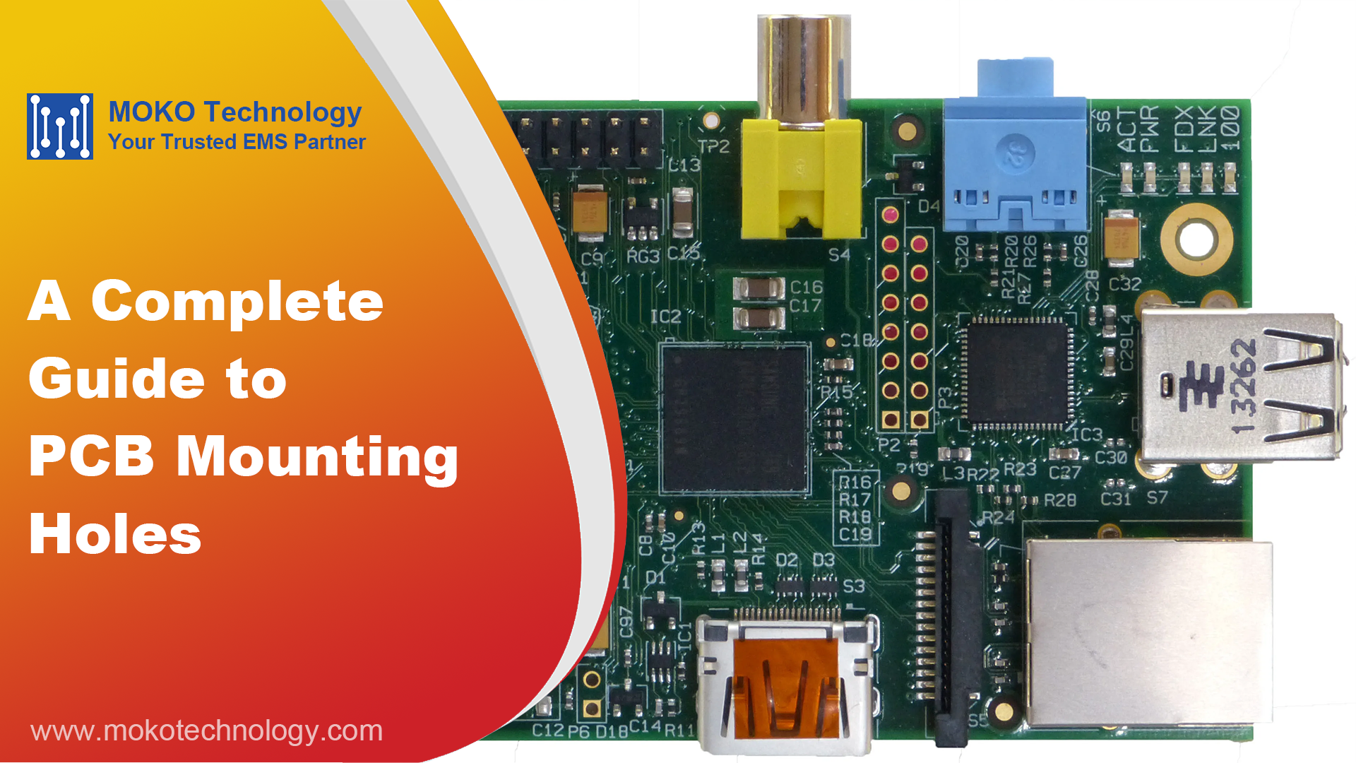
What Are PCB Mounting Holes?
PCB mounting holes refer to the holes that are drilled through the printed circuit board (PCB), so the board can be fixed on a chassis or enclosure. Typically, these holes are positioned at the board’s corners and have a larger diameter compared to other holes on the board. And a copper pad or annular ring surrounds them to ensure a stable connection between the mounting hardware and the board.
Two Types of Mounting Holes
Mounting holes can be classified into two types based on their conductive layer: plated and non-plated mounting holes. Plated mounting holes are not only useful for creating electrical connections between different layers of the PCB, but they also serve as secure anchor points for screws, bolts, or other hardware that make components firmly fixed on the board. As to non-plated mounting holes, they are mainly intended for mechanical applications and do not require a conductive layer. The un-plated mounting holes may need to be kept isolated and require a keep-out zone to prevent any interference with other components or traces on the board.
PTH vs. NPTH PCB Mounting Holes
| Feature | PTH | NPTH |
| Copper plating | Yes | No |
| Electrical connection | Electrically conductive | Electrically isolated |
| Grounding capability | Can be grounded | Usually isolated |
| Manufacturing complexity | Requires plating process | Simpler fabrication |
| Cost | Slightly higher | Lower |

PCB Mounting Hole Sizes (Clearance for Screws)
The table below provides recommended hole diameters for common screw sizes.
| Screw Size | Clearance Hole Size (mm) | ||
| Close Fit | Normal Fit | Loose Fit | |
| M1.6 | 1.7 | 1.8 | 2.0 |
| M2 | 2.2 | 2.4 | 2.6 |
| M2.5 | 2.7 | 2.9 | 3.1 |
| M3 | 3.2 | 3.4 | 3.6 |
| M4 | 4.3 | 4.5 | 4.8 |
| M5 | 5.3 | 5.5 | 5.8 |
| M6 | 6.4 | 6.6 | 7.0 |
How to Make Mounting Holes on PCB?
During the manufacturing process, PCB mounting holes are drilled by CNC machines using carbide drill bits. For non-plated mounting holes, when drilling is finished, the hole is also ready. However, plated mounting holes need to undergo copper electroplating to create an electrically conductive barrel after drilling.
PCB manufacturers commonly require hole specifications to be clearly defined in your Gerber drill file, including hole type (PTH or NPTH), hole size, clearance, etc.
PCB Mounting Holes Design Considerations

Mounting Hole Quantity and Placement
At least three holes are recommended to avoid movements or vibrations of PCB. The three-point mounting structure distributes mechanical stress evenly, giving stable mechanical support. Holes to mount also need to be positioned to distribute the mechanical forces equally, particularly where corners or heavy components are included.
| Board Size | Recommended Mounting Strategy |
| Small | Four corner mounting holes |
| Medium | Four corners + additional edge support |
| Large | Typically spaced 80–150 mm (based on PCB mechanical requirements) + center support |
Hole Diameter and Clearance
Always drill a hole size to fit the fastener with a proper clearance. The finished hole size is equal to the hole size for NPTH holes. For PTH holes, the finished hole size is smaller than the drill size due to copper plating thickness. Thus, the drill diameter should be increased accordingly.
PTH vs. NPTH
Plated or non-plated mounting holes can be used based on the design requirements. Non-plated holes are suitable for mechanical mounting, but cannot provide grounding capability. Plated holes can be used to create a ground net for EMI shielding and add mechanical stability.
PCB Thickness Compatibility
When designing the mounting holes, it is important to consider the thickness of the board. To guarantee a stable and safe mount, the holes’ depth and diameter must match the PCB thickness. If using thicker boards (2mm or 2.4mm), check for adequate standoffs and screw thread engagement depth.
Annular Ring Requirements
Based on the capability of the PCB manufacturer and reliability requirements, PTH mounting holes should have a minimum annular ring width of 0.2 mm, according to IPC-2221.
Grounding and EMI Considerations
If your design has the need for EMI shielding, connect PTH mounting holes to the ground plane. When used with a metal screw and stand off, a low impedance path to chassis ground is created.
Final Thoughts
In conclusion, PCB mounting holes are a critical aspect of any PCB design that requires mechanical components to be attached securely to the board. By following the design rules outlined in this blog, you can create mounting holes that will ensure a secure and stable mount for your mechanical components. However, if you lack relevant experience and expertise in PCB mounting holes, it would be better to consult experts in this field. TestPcbas has been focusing on PCB design and manufacturing for more than ten years, we can provide you with professional guidance to ensure the success of your project.
FAQs
Why are mounting holes sometimes surrounded by small vias on a PCB?
These vias are added around PCB mounting holes to improve mechanical strength, electrical grounding, and thermal performance.
Should you ground PCB mounting holes?
Actually, it depends on your design requirements. PCB mounting holes should be grounded when the design requires EMI shielding, chassis grounding, or improved electrical stability.
What is the difference between countersunk and counterbore holes?
Countersunk holes use a conical recess for flat-head screws, while counterbore holes use a flat-bottom recess for cylindrical screw heads or nuts.
Tooling holes vs. mounting holes: what is the difference?
Tooling holes typically are non-plated holes and are designed to align the board during drilling, stencil printing, and automated assembly. These are generally located on the panel rails and are discarded once the boards are de-paneled. Mounting holes are used in the PCB enclosure and designed to fit specific hardware, like screws.
 Arabic
 Dutch
Dutch English
 French
 German
 Italian
 Japanese
 Korean
 Portuguese
 Russian
 Spanish