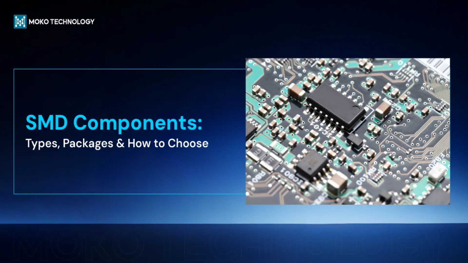
Walk into any electronic laboratory today, and you will find SMD components (Surface Mount Devices). These small parts are hard to see with the naked eye —yet they are the backbone of all the equipment that you use. Understanding how to identify and use these components is one of the essential things to learn as a PCB engineer.
With this guide, you will learn the major types of SMD components, component sizes and codes, and how to select the correct component in your PCB design.
What Are SMD Components?
SMD components are electronic components that are mounted directly onto the surface of a printed circuit board (PCB). They are featured with compact sizes and are the primary choice in the modern electronics production.
Advantages and Limitations of SMD Components
Surface mount devices have a number of useful benefits:
- They are lightweight and compact, making them the preferred option in portable and space constraint devices.
- Can be mounted on each side of PCBs so as to increas the layout density.
- Enhancing the manufacturing efficiency by integrating into automated process
Nevertheless, there are also limitations associated with the SMD components:
- Difficult to assemble manually because they are so small, and the professional tools are needed.
- These components are difficult to check and fix.
- Inapplicable to high power or extreme environments.
SMD vs Through-Hole (THT) Components
Prior to the advent of SMD, engineers mainly used THT components. To this day, both of them play indispensable roles in modern electronics manufacturing. So, what exactly are the differences between them? Check the table below:
| Feature | SMD | THT |
| Size | Compact, lightweight | Larger, heavier |
| PCB space | Mounts on both sides | Single side only |
| Assembly | Highly automated | Manual or semi-automated |
| Soldering | Reflow soldering | Wave or hand soldering |
| Mechanical strength | Lower, vibration-sensitive | Higher, more robust |
| Heat dissipation | Limited | Better |
| Rework & repair | Difficult, requires tools | Easier by hand |
| Cost | Lower at scale | Higher labor cost |
Further reading: Through Hole Vs. Surface Mount: How to Choose the Right Method
Common SMD Component Types
Although there are hundreds of SMD variants, the majority of circuits use the same basic set of components. Here’s what you’ll encounter most often:
Passive SMD Components

First, we need to know what passive SMD components are: These are the components that do not require external source of power. They are able to store, dissipate or even filter energy in a circuit. Common SMD components types include:
- Resistors
SMD resistors are used to control and limit the amount of electric current flowing within a circuit. Their unit is ohms (Ω), and the resistance range are from 1 Ω to 10 MΩ.
Popular resistor types include thick film resistors, thin film resistors, and current sense resistors.
- Capacitors
Capacitors are one of the most important components used in PCBs to store electric energy, filter noise and stabilize the voltage. Their value is measured in farads (F), although most of them have a capacitance value in the 1 pF – 100 µF range. Common types of SMD capacitors are ceramic capacitors, tantalum capacitors, film capacitor, and electrolytic capacitors.
- Inductors
The functions of SMD inductors are the storage of energy in a magnetic field, filtering signals, and converting power. Their value is measured in henries(H), and normally their inductance ranges from 1 nH to 1000 µH. Widely used inductor types include wirewound inductors, multilayer inductors, ferrite bead inductors.
Active SMD Components

Active components need to be powered by an external power source to perform their functions, and the following are the three most commonly used active components:
- Diodes
Diodes are used in PCBs to control current flow, which ensures that the current flows in only one direction. They play a key role in circuit protection and power management. The common kinds of diodes are the rectifier, Schottky, Zener, and LED diodes.
- Transistors
The printed circuit boards use SMD transistor for switching and amplification of electrical signals, which are the heart of the analog and digital circuits. Examples of common types of transistors are BJTs, MOSFETs and IGBTs.
- Integrated Circuits (ICs)
ICs integrate multiple electronic components into a single chip; hence, they are able to perform complex functions in a compact size. They are considered to be the heart of an electronic system. IC types such as microcontrollers (MCUs), op-amps, logic ICs, and power management ICs are widely used.
SMD Component Summary
The table below provides a quick reference of the most common surface-mount components used in PCB design and assembly.
| Component | Function | Common Packages | Typical Applications |
| Resistors | Limit current, control voltage | 0402, 0603, 0805 | Current limiting, voltage dividers |
| Capacitors | Store energy, filter noise | 0402, 0603, 0805 | Decoupling, filtering, signal coupling |
| Inductors | Store magnetic energy | 0603, 0805 | DC-DC, EMI filtering |
| Diodes | Allow one-way current flow | SOD-123, SOD-323 | Rectification, protection |
| Transistors | Switch/amplify signals | SOT-23, SOT-223 | Switching, amplification |
| ICs | Process signals, control operations | SOIC, QFN, BGA | Processing, control |
SMD Package Sizes and Codes
Surface mount devices are packaged differently with varying sizes and codes that indicate their electrical values. And It is necessary for engineers to learn how to identify these key parameters.
Standard SMD Package Sizes
SMD packages are typically coded by using four digits, indicating length and width of the components in inches. For example, the code “0402” means that the length is 0.04 inches and the width is 0.02 inches. The table below lists more instances for better understanding:
| Package | Inches | Millimeters | Typical Use |
| 01005 | 0.01 × 0.005 | 0.4 × 0.2 | Ultra-high density designs, wearable devices |
| 0201 | 0.02 × 0.01 | 0.6 × 0.3 | High-density PCBs, mobile devices |
| 0402 | 0.04 × 0.02 | 1.0 × 0.5 | Consumer electronics, compact designs |
| 0603 | 0.06 × 0.03 | 1.6 × 0.8 | General-purpose circuits |
| 0805 | 0.08 × 0.05 | 2.0 × 1.25 | Moderate power, easier assembly |
| 1206 | 0.12 × 0.06 | 3.2 × 1.6 | Higher power, thermal stability |
SMD Resistor Codes
There are two forms to code the value of resistors:
- Three-digit code (most common): the first two digit are significant figures and the third one is the multiplier.For instance:
103 = 10 × 10³ = 10 kΩ
472 = 47 × 10² = 4.7 kΩ
- Four digit code (precision resistors): the first three digits are significant figures, and the fourth is the multiplier.For example: 1001 means 100 × 10¹, so the resistance value is 1 kΩ.
The EIA-96 alphanumeric coding system is also used on some of the precision resistors.
SMD Capacitor Codes
Many small SMD capacitors are too small to be marked. In case there are some codes, they use a three-digit system with the first two digits are significant figures and the final one is the multiplier in picofarads.
104 = 10 × 10⁴ pF = 100 nF
225 = 22 × 10⁵ pF = 2.2 µF
In practice, engineers often rely on datasheets or BOM information to identify capacitor values.
SMD Inductor Codes
Unlike resistors and capacitors, the markings of inductors are not standardized. Different component manufacturers have different codes; some use three-digit codes and some use four-digit codes. Therefore, it is necessary to check the component datasheet to ensure the values.
Reading this far, you might be wondering: how can I distinguish whether a “code” represents a size or a value? Well, the SMD package size codes would not be printed on the components. These codes are used in BOMs. And the code you see on the components means the electrical values.

How to Identify SMD Components
When trying to analyze an unfamiliar PCB, a magnifying glass or inspection microscope is your best friend. But simply being able to read the tiny markings is the first step. Many components give clues based on their markings, polarity, and package style:
- SMD Resistors: These components are usually marked with 3- or 4-digit codes, and most of them are rectangular in shape. They are non-polarized components.
- SMD Capacitors: Tantalum capacitors are usually marked with a 3-digit code and a polarity mark (a line indicating the positive terminal). However, most ceramic capacitors have no markings, so identifying such components requires checking the datasheet.
- SMD Diodes: Marked with a line on one side (cathode). These markings help determine the direction of current flow.
- SMD Transistors: Transistors are typically marked by using 2–3 character codes like A1C or 2N, and are packaged in SOT-23 or SC-70 formats. These codes are typically manufacturer-specific.
If the part markings aren’t visible, measuring the package dimensions can provide clues on component type and values based on industry standards. Additionally, checking the BOM, schematics, or component datasheets for accurate identification is always a good method.
Soldering and Assembly of SMD Components

SMD assembly usually utilizes the Surface Mount Technology (SMT) and it generally involves the following 4 step:
Step 1: Solder Paste Printing
Applying solder paste to the PCB pads using SMT stencils, making sure the solder is accurately put in the location where the surface mounted components would be soldered.
Step 2: Pick-and-place
Here, SMT machines would place the parts on the board at the correct positions based on the design file.
Step 3: Reflow Soldering
Then circuit boards with components on them would be put into a reflow oven to melt the solder. When it is cooled, the solder would harden and form stable solder joints.
Step 4: Inspection and quality control.
The final process is to examine the quality of SMD soldering, and AOI (Automated Optical Inspection) and X-ray inspection are normally conducted to check the visible and invisible defects.
Although the majority of SMD are assembled using SMT, manual soldering is still needed in the prototyping and repair of certain components.
How to Choose SMD Components
Here are three key considerations when choosing the right SMD components for your PCB design:
- Electrical Characteristics
It’s important to ensure that the core specs of components, such as resistance, capacitance, inductance, voltage rating, and power rating can match your requirements. For capacitors, making sure its working voltage is below 80% of the rated value; for resistors, select a power rating at least twice the expected dissipation to ensure long-term reliability.
- Physical Dimensions
The component should fit the available space on your PCB. Most designs typically start with standard packages like 0603 or 0805 that are easy to assemble and have compact sizes. If the space is limited, consider to use 0201.
- Reliability & Environment
Make sure the working temperature of SMDs can matches your application. If these components are used for consumer electronics, then choosing components that operate from 0°C to 70°C is reasonable. If they are used in harsh environments, then choose components that can withstand such extreme temperatures.
Frequently Asked Questions
What is the difference between SMT and SMD?
Surface Mount Device (SMD) actually is the name of the component itself, whereas the surface mount technology (SMT) is the process and methodology that is applied to mount these SMD components to a PCB.
Are SMD components better than through-hole?
They are more suitable for high-density and automated production, whereas THT has better mechanical strength. There is no absolute “better” option, choosing them based on your application.
Can SMD components be soldered by hand?
Yes, they can be soldered by hand though it requires practice and the right tools such as fine-tipped soldering iron, flux, and tweezers.
How do I identify a SMD component?
Surface-mounted components can be identified by their markings, package size, and physical features. Additionally, you can check the component datasheet.
 Arabic
 Dutch
Dutch English
 French
 German
 Italian
 Japanese
 Korean
 Portuguese
 Russian
 Spanish