Just like the light-emitting diode, which served exclusively as an indicator lamp for decades, PCB has also left its shadowy existence and has rapidly advanced to a multifunctional element within an electronic system. However, along with the development of integration technology, the total power density of electronic components continues to increase, but the physical size of electronic components and electronic devices is designed to be smaller and smaller that would cause the increased heat flux density around the device, which would affect the performance of electronic components, so it is necessary to find a more efficient way to manage the thermal conductivity. In this blog, we will focus on the FR4 thermal conductivity as it is one of the most widely used PCB materials.
What is Thermal Conductivity?
The thermal conductivity of a material like FR4 refers to how effectively it can transfer heat energy via conduction. It is quantified by the rate of heat flow through a specific thickness of the material for a given temperature gradient. The units used to measure thermal conductivity are Watts per meter-Kelvin (W/mK). Materials with higher values conduct heat more readily than insulators with lower thermal conductivity. Metals tend to have the highest thermal conductivity, while plastics and ceramics are on the lower end of the scale. For heat to conduct from a heat source to a heat sink, the material between them must have sufficient thermal conductivity. The quantity of thermal energy flowing between two objects is determined by both the temperature gradient and the particular conductive qualities of those materials. Heat flows spontaneously from hotter matter to colder matter. When two objects at different temperatures make contact, thermal energy diffuses from the hotter one into the cooler one. This heat transfer continues until the temperature difference decreases and thermal equilibrium is attained. Managing this heat conduction is crucial in electronics to prevent excessive component heating and ensure proper performance. The combination of thermally conductive traces and insulating substrate is a fundamental consideration in PCB design.
Here is the equation of thermal conductivity:
K = (Q × L) / (A × ΔT)
Where:
| Symbol | Meaning | Unit |
| K | Thermal conductivity of the material | W/m·K |
| Q | Rate of heat flow through the material | Watts (W) |
| L | Thickness of the material | Meters (m) |
| A | Cross-sectional area through which heat flows | m² |
| ΔT | Temperature drop across the material | Kelvin (K) |
Technical Characteristics of FR4 Thermal Conductivity
The FR4 PCB thermal conductivity is relatively low, and it varies depending on the specific grade and manufacturer. Here are some general technical characteristics of FR4 PCB thermal conductivity:
- Thermal Conductivity Value
The thermal conductivity of FR4 typically ranges from 0.3 to 0.4 W/m·K (watts per meter-kelvin). This is relatively low compared to materials like aluminum or copper, which have much higher thermal conductivities.
- Anisotropic Conductivity
FR4 is anisotropic, meaning it has different thermal conductivity values in different directions.
In-Plane Conduction (X–Y axis): Heat flows along relatively continuous glass fiber paths, thereby achieving more efficient conduction.
Through-Plane Conduction (Z-axis): Heat must traverse multiple layers of resin and resin-fiber interfaces. Each layer generates thermal resistance, which severely impedes heat flow.
It is an important characteristic that requires special attention during the PCB thermal design process, as effective thermal management methods must bypass the bottleneck of through-plane conduction. For example, shortening the heat transfer path, which is related to reducing the board thickness. Or, offering a low-resistance channel, such as thermal vias.
- Temperature Dependence
The thermal conductivity of FR4 is also temperature-dependent. FR4 displays a thermal conductivity that lessens as its temperature increases. This reduction in conductive heat transfer under higher temperature conditions can impair FR4’s ability to spread and sink away excess heat.
- Thickness Matters
The thickness of the FR4 PCB can influence its thermal performance. Thicker PCBs will have higher thermal resistance due to the longer heat conduction path through the material. Want to know how to choose PCB thickness? Check out our other blog: https://www.testpcbas.com/pcb-thickness/
- FR4 Grade
There are different grades of FR4 available, and the thermal conductivity may vary slightly between them. For example, high-Tg (glass transition temperature) FR4 materials may have slightly different thermal properties compared to standard FR4.

FIND THE BEST CRAFTED FR4
6 Proven Methods to Improve FR4 PCB Thermal Management
FR4 possesses low thermal conductivity, so the substrate itself cannot conduct heat efficiently. Here are six effective methods to enhance FR4 PCB thermal management.
Method 1: Thermal Vias
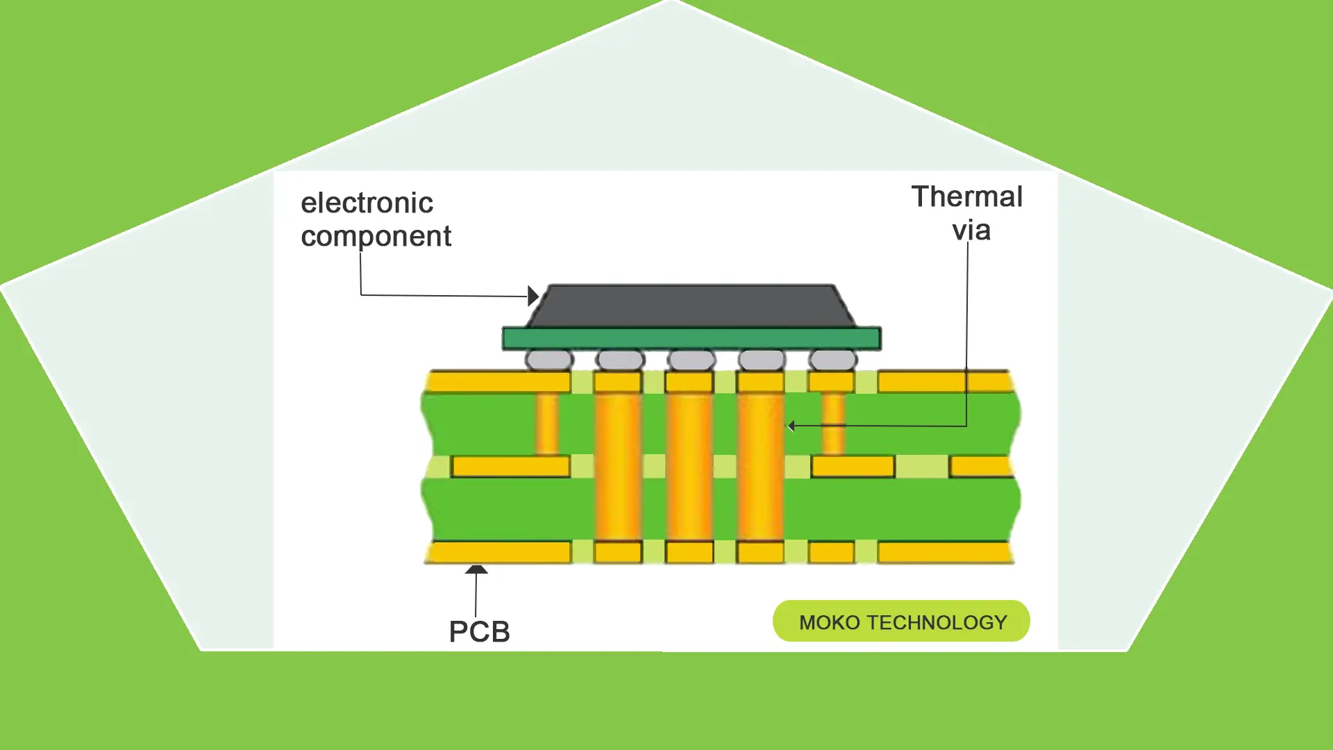
It’s one of the most useful ways to manage the heat in the FR-4 PCB. Thermal vias are small holes that are copper-plated. The heat could be transferred vertically across the PCB layers through these vias. These vias are direct thermal tunnels, highly reducing the critical and sensitive areas’ temperature, down to 10-20°C.
These thermal vias have diameters ranging from 0.3 to 0.5 mm and a pitch of 1 to 1.5 mm. If they are arranged in a grid pattern, it’s more effective than isolated vias to manage heat. They can be filled in the holes with conductive epoxy or copper, and this enhances their thermal conductivity. Thermal vias are positioned directly beneath or in the vicinity of high-power components, such as power transistors or integrated circuits.
Method 2: Copper Pour and Planes
In PCB thermal design, large copper pours, or power/ground planes, may act as efficient heat spreaders. Copper has high thermal conductivity, which is approximately 400 W/m-K, as opposed to FR-4, which is between 0.3 and 0.8 W/m-K.
PCB components generate heat, carried through the PCB into the copper pour, and quickly diffuses throughout the plane. This redistribution of the localized hotspots in a broader region, in effect, minimizes heat flux. In real-world design, FR4 PCB thermal management is typically achieved by laying down continuous, large-area ground or power planes, combined with thermal vias design.
Method 3: Thermal Interface Materials
Thermal Interface Materials (TIMs) are affordable materials employed to enhance the thermal conductivity of contact interfaces. The contact surfaces of two parts may look flat at first glance. In fact, there are minute cracks or pores. Air occupies the spaces, and it is a poor conductor of heat. TIM uses a substance with a greater thermal conductivity than air to fill the spaces between contact surfaces.
TIMs are available in the market in various kinds. Common types include:
- Thermal tapes
- Thermalgreases/paste
- Thermalgels/adhesives
- Thermal pads
Method 4: Embed Copper Wire into FR4 PCB
TestPcbas takes a different approach with »HSMtec«. The technology, which is qualified in accordance with DINEN60068-2-14 and JEDECA101-A and audited for aviation and automotive, is selective: only where high currents are supposed to flow through the printed circuit board does thick copper.

FIND OUT HOW TO SELECT THE RIGHT PCB ASSEMBLY FOR YOUR PROJECT
Currently, 500µm high profiles with widths from 2.0mm to 12mm are available in variable lengths, with wires a diameter of 500µm has become established. The solid copper elements that are firmly bonded to the conductor patterns can be applied directly to the base copper using ultrasound connection technology and integrated into any layer of a multilayer using FR4 base material. There are several reasons why copper is used: It has twice the thermal conductivity compared to aluminum and thus ensures rapid heat dissipation without insulating intermediate layers underneath the LED heat pad.
| Material | Thermal conductivity λ [W / mk] |
| Copper RA | 300 |
| aluminum alloy | 150 |
| solder | 51 |
| Ceramic (LED) | 24 |
| FR4 | 0.25 |
| Air (resting) | 0.026 |
Table 1: Thermal conductivity of the materials involved
Another advantage of copper and the circuit board base material FR4 are the thermal expansion properties (Table 2): Especially in connection with ceramic LEDs, circuit boards based on copper or FR4 have a high resistance to thermal stresses, which depend on environmental or operating conditions and others Temperature cycles, such as for “intelligent” lighting controls.
| Material | Expansion coefficient [ppm / K] |
| aluminum | 24 |
| solder | approx. 22 |
| copper | 16 |
| FR4 | 13-17 |
| Al2O3 (LED) | 7 |
| AlN (LED) | 4 |
Table 2: Thermal expansion coefficient in the X / Y direction
In this way, the lifespan and reliability of the entire lighting unit can be significantly increased compared to conventional metal core PCB based on aluminum.
Method 5: Active Cooling Techniques
Fans can enhance the movement of air over the PCB board and enhance convective heat transfer. In practice, a small fan can lower the temperature of components by about 20 to 30 o C. Liquid cooling systems work better with high-power equipment.
Method 6: Switching to a High Thermal Conductivity Substrate
Sometimes, the correct approach is not to attempt to circumvent the thermal limitations of FR4, but rather to replace it. Standard FR4 has low thermal conductivity, and high Tg FR4 has relatively higher thermal conductivity and resistance to thermal cycling stress.
Besides FR4, it is possible to choose other high-thermal-conductivity materials as well. It is as important to know when to make that call as any design technique. A basic table is provided below.
| Material | Thermal Conductivity | Relative Cost |
| Standard FR4 | 0.3 – 0.4 W/m·K | Low |
| High-Tg FR4 | Up to 0.8 W/m·K | Low–Medium |
| Aluminum | 150 – 230W/m·K | Medium |
| Copper | 400 W/m·K | Medium–High |
| Alumina (Al₂O₃) | 24 – 30W/m·K | High |
| Aluminum nitride (AlN) | 170 – 250 W/m·K | Very High |
| Rogers Laminates | 0.7 – 1.7 W/m·K | High |
Frequently Asked Questions
What is the coefficient of thermal expansion (CTE) of FR4?
The CTE of FR4 is not the same in the X-Y and Z directions and is as follows:
X-Y direction: ~14–18 ppm/°C
Z direction: ~70–100 ppm/°C
What is the thermal conductivity of copper in PCBs?
Compared to FR4, copper has a much higher thermal conductivity of about 400 W/m·K.
What are the key mechanical properties of FR4?
The essential mechanical properties include tensile strength, flexural strength, and excellent dimensional stability.
What are FR–4 PCBs?
FR4 PCBs are made from flame-retardant fiberglass-reinforced epoxy laminate. They provide electrical insulation, mechanical strength, and cost efficiency.
What are the different types of FR4 materials?
FR4 materials come in a variety of types, including halogen-free FR4, standard FR4, and high Tg FR4.
Conclusion
FR4 is a commonly used material for PCB manufacturing as it is economical and has great properties that can be utilized in different applications. But compared to other materials, it has poorer performance in the thermal conductivity. Thus, it is necessary for manufacturers to understand the thermal conductivity features of FR4 and learn how to manage it, which can not only help them reduce cost, but also improve the quality of their products. If you still have questions about the FR4 PCB thermal management, you can go to TestPcbas to get the answer.